
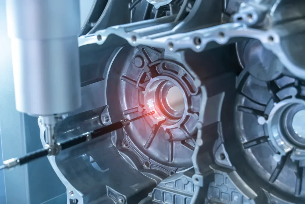
When manufacturing parts with high pressure die casting, there is a risk that porosity or impurities may form in critical areas, much to the frustration of every product developer. Some defects show up on the surface. Others stay hidden until a part is machined, pressure tested, or put into service.
Most die casting defects trace back to two sources: how the casting fills and solidifies, and the quality of the molten aluminum. Knowing the causes tells you what to ask your die caster when you request a quote.
General Die Casters, part of the GD Casting Group, breaks down what causes porosity and impurities, how die casters control them through design and process control, and what other common defects to watch for.
The Short Answer
Process controls to manage porosity and metal quality are critical. Gas porosity forms when air gets trapped as metal fills the die, and shrink porosity forms when the casting cools unevenly. Oxides, sludge, and hydrogen in the molten aluminum cause hard spots and gas pores. Flash, cold shuts, blisters, soldering, and cracks also show up.
Why Does a Die Casting Have Porosity?
A die casting is created in seconds. Molten aluminum is forced into the die cavity in less than 60 milliseconds and begins to solidify as soon as it touches the surface of the steel. The casting solidifies in just a few seconds and can be removed from the die.
An aluminum casting solidifies much like ice crystals crackling along your car window. Once the first aluminum crystals form on the die surface, they continue to grow until the entire casting is solid.
The skin of the casting is the first aluminum to solidify against the die steel. This material is dense and largely free of porosity. It is a pressure tight matrix of aluminum. The skin of a casting is typically 1 millimeter (.040”) thick.
Unfortunately, the process becomes more chaotic as solidification progresses from there.
The progression of solidification is largely determined by the geometry of the casting. The part design plays a significant role in the size and location of porosity in the final part.
One of the biggest factors in solidification (and porosity) is variation in wall thickness throughout the casting. Inconsistent wall thickness affects the casting in two ways:
- Entrapped air during filling (gas porosity)
- Internal voids due to uneven solidification (shrink porosity)
Entrapped Air (Gas Porosity)
Air in the die cavity must be evacuated through vents or vacuum valves during filling, or it can remain trapped in the casting as porosity. Porosity formed as molten aluminum collects air during filling is called gas porosity. Hydrogen in the molten aluminum can also add to gas porosity.
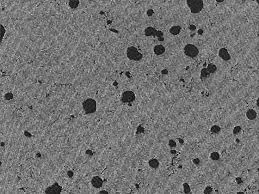
Gas porosity on a polished surface of a die casting. Gas porosity appears round and smooth. It forms as the aluminum solidifies around pockets of air.
A casting designed with consistent wall thickness allows the air in the cavity to be pushed ahead of the metal flow and out of the vents. This results in a casting with a very small amount of trapped air.
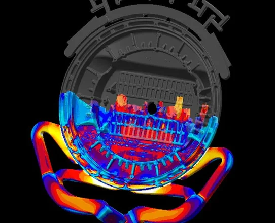
A simulation of an ideal fill. A laminar metal flow pushes air toward the vents without entrapment.
A casting with inconsistent wall thickness is more likely to trap air. Molten metal can collect air as it flows through the die cavity. This air can become gas porosity if it is not washed out into overflows.
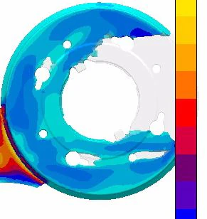
A simulation showing air trapped in the metal flow, which can result in porosity.
Controlling Gas Porosity With Die Design
The die caster engineers a runner and vent design to minimize the amount of trapped air in the casting. Flow simulation software such as MAGMASOFT is used to optimize the runner and venting system for each casting. At General Die Casters, our engineers use it during the upfront design evaluation to model and test ideas before the die is built.
Internal Voids From Uneven Solidification (Shrink Porosity)
Shrink porosity is sharp and jagged. It forms as the casting shrinks unevenly during solidification, which opens internal voids inside the casting.
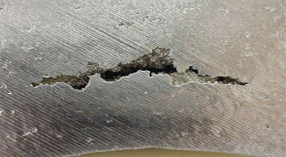
Uneven solidification opens internal voids inside the casting called shrink porosity.
The die caster has two main tools to control shrink porosity: internal cooling and heating lines in the die, and intensification pressure.
Internal Cooling and Heating Lines
The die caster designs a die with strategically placed heating and cooling lines to promote even solidification in the casting.
MAGMASOFT solidification simulation shows which areas of the casting will be last to solidify. These areas typically contain the highest levels of porosity. The die caster then places cooling lines as close to these areas as possible to promote more even solidification.
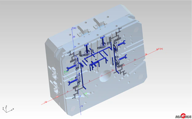
A 3-D model of a cover die showing the internal cooling channels.
Intensification Pressure
Die casting machines use high pressure to force molten aluminum into shrink voids during solidification. The pressure can be as high as 12,000 PSI inside the die during solidification.
A shot profile. The third trace represents pressure over time and shows the intensification pressure rise after the cavities are filled. The caster uses this data to closely monitor and control intensification pressure during production.
Unfortunately, the intensification pathway is only open for a few seconds before the gate inlets solidify. Once the gates are solid, the casting shrinks based on its geometry and the die temperature.
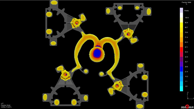
A simulation showing unsolidified areas of the casting after the gates close. Shrink porosity can form in these areas.
How Clean Are Your Castings?
If you have experienced impurities in your die castings, you understand that they can be a costly defect. Hidden impurities can damage or destroy machining tools and can even affect the integrity of the part. Because impurities are not visible on the surface of the casting, your options are limited once you find them. Large quantities of parts may need to be scrapped to avoid damaging expensive machining tools.
While individual castings can be melted and tested for quality, there are better options. A thorough evaluation of your supplier’s metal handling systems shows whether they can consistently produce high quality castings. First, it helps to understand the 3 primary impurities in aluminum:
- Aluminum oxides
- Sludge
- Hydrogen
Aluminum Oxides
Aluminum is a very reactive element and likes to react with oxygen. Any exposed surface of aluminum immediately reacts with oxygen to form aluminum oxide (Al₂O₃). If you have an aluminum casting sitting on your desk, the entire outside surface is an aluminum oxide skin.
The surface of the molten aluminum bath is also covered in a thin layer of aluminum oxide. These oxides become entrained in the bath when turbulence occurs inside the furnace. Turbulence or splashing can come from adding raw material (ingot), ladling metal for casting, cleaning the furnace, and impingement of the burner flame. Turbulence ripples the oxide surface and exposes fresh aluminum to oxidation. Constant turbulence can quickly create large quantities of oxides in the furnace.
This oxidation reaction speeds up as the temperature of the aluminum and oxygen increases. The air temperature inside an aluminum melting furnace can exceed 2,000°F. These conditions are ideal for rapid oxide growth on the surface of the bath and on the refractory walls of the furnace. Once an oxide has formed, it can keep growing if the right conditions exist. Oxides can build up quickly in furnaces that are not maintained.
If oxides are not removed with regular cleaning, they continue to grow and increase in density. Aluminum oxides can eventually become corundum, which is nearly as hard as diamond. These “hard spots” can find their way into a casting and damage machining tools during secondary machining operations.
Sludge
Sludge is sediment of iron, manganese, and chromium that has come out of solution. Sludge forms when the temperature of the molten metal is too low to keep these elements in solution. Sludge can make its way into the ladle cup and become trapped in a casting. Like corundum, sludge can damage or break machining tools during secondary machining operations.
Sludge factor is used to determine the likelihood of sludge forming. It is calculated with this equation:
Sludge Factor = (1 × Fe%) + (2 × Mn%) + (3 × Cr%)
Sludging is typically minimal when the sludge factor is less than 2.0 and the furnace temperature stays above 1,200°F. At General Die Casters, we check sludge factor daily in each melting furnace with a spectrometer. It should also be specified when purchasing raw material.
Hydrogen
Hydrogen is absorbed into molten aluminum from the atmosphere inside the furnace. While hydrogen content is very important in gravity die casting, it is less of a concern in pressure die casting. The high pressures used in die casting can compress normal amounts of hydrogen. Your die caster should still watch hydrogen content in their furnaces if they produce high integrity die castings.
How Die Casters Keep Molten Aluminum Clean
A die caster controls aluminum impurities in the furnace with consistent cleaning and maintenance.
Flux
Flux is used to remove oxides and impurities from molten aluminum. It reacts with aluminum oxides and breaks the bond, freeing the aluminum. The oxides then float to the surface of the bath. This light, grey, ashy material is called dross. Dross is skimmed from the surface and removed from the furnace.
Flux can either be raked into the surface of the aluminum or injected beneath the surface with nitrogen gas. Either can be effective. Injecting flux with nitrogen, the method General Die Casters uses, has the added benefit of removing hydrogen from the molten aluminum.
Mechanical Scraping of the Furnace Walls
This is another important step in cleaning a furnace. Cleaning tools are used to scrape aluminum oxide buildup from the walls of the furnace. Remove oxide growth on the furnace walls regularly, or it can keep growing.
Regular cleaning with flux, nitrogen, and properly designed tools is the first step toward metal quality.
Furnace Maintenance
A furnace maintenance program is also crucial for high quality metal. Gas powered furnaces use high flow air blowers to generate the heat needed to melt and hold molten aluminum. Tune gas burners to the proper air and gas ratio. A lean burner (more air than gas) provides excess oxygen and promotes aluminum oxide growth.
Monitor the temperature of the furnace’s outside shell as part of the maintenance program. A high shell temperature can be a sign of a crack or worn area in the refractory wall. The furnace is less efficient when heat escapes through damaged walls, so the burners have to generate more heat to maintain metal temperature. That added heat promotes aluminum oxide buildup inside the furnace.
Empty, clean, inspect, and patch furnaces regularly as part of the maintenance schedule. Sludge and oxide sediment on the furnace floor is removed during cold cleaning.
How Do You Know if the Metal Is Clean?
General Die Casters checks metal quality in-house with two common tools: the K-mold and the reduced pressure tester.
K-Mold
A K-mold is a small mold used to cast a rectangular bar. The bar is designed to break easily so the fractured surface can be inspected. Visible oxides on these surfaces are a sign of oxides in the furnace.
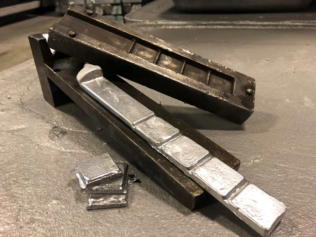
A K-mold with test castings.
Reduced Pressure Tester
A reduced pressure tester is used to check hydrogen levels in the aluminum bath. A small disc is poured and solidified under a vacuum. The disc is sectioned and examined for the size and number of gas pores. This is a useful check that cleaning practices are giving the desired results.
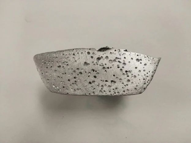
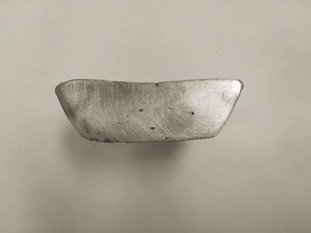
Quantifying metal quality can be challenging. A reliable way to judge the metal going into your castings is to evaluate your caster’s metal quality procedures. A detailed furnace cleaning and maintenance program that is being followed is a good sign of consistent, high quality metal.
Other Common Die Casting Defects
Buyers may also run into these defects.
Flash
Flash is a thin fin of metal that squeezes out at the parting line or around slides and ejector pins. It usually comes off in trimming, but heavy or growing flash is often a sign the die needs maintenance.
Cold Shuts
A cold shut is a seam on the surface where two flows of metal met but did not fully fuse, usually because the metal or die ran too cold or the fill was too slow.
Blisters
Blisters are raised bumps caused by gas trapped just under the skin. You may not see them until after heat treating or painting, when the gas expands. If your part will be heat treated or painted, mention it when you request a quote.
Soldering
Soldering happens when aluminum sticks to the die steel and tears the casting surface as the part is ejected. Die temperature, die lubricant, and draft angles all play a part.
Cracks
Cracks tend to form at sharp corners or where thick and thin sections meet. Add generous fillets and keep wall thickness even to reduce the risk.
Common Defects at a Glance
| Defect | What It Looks Like | Common Cause | How It’s Controlled |
|---|---|---|---|
| Gas porosity | Round, smooth voids | Air trapped during filling | Consistent walls, runner and vent design, flow simulation |
| Shrink porosity | Sharp, jagged voids | Uneven solidification | Cooling lines, intensification pressure, even wall thickness |
| Aluminum oxides | Hard spots found during machining | Turbulence and heat in the furnace | Flux, wall scraping, burner tuning |
| Sludge | Hard spots found during machining | Iron, manganese, and chromium dropping out of solution | Sludge factor under 2.0, furnace above 1,200°F |
| Hydrogen | Gas pores | Hydrogen absorbed from the furnace atmosphere | Nitrogen flux injection, reduced pressure testing |
| Flash | Thin metal at the parting line | Die wear or poor lockup | Die maintenance, trimming |
| Cold shuts | Seams or lines on the surface | Low metal or die temperature, slow fill | Temperature and fill control |
| Blisters | Raised bumps on the surface | Gas trapped under the skin | Venting, vacuum, fill control |
| Soldering | Torn or rough surface | Aluminum sticking to the die | Die temperature, lubricant, draft |
| Cracks | Breaks at corners or section changes | Stress as the casting shrinks | Fillets, even wall thickness |
Can You Make a Die Casting Without Porosity?
Not completely. Porosity cannot be eliminated, but it can be controlled through careful design, process control, and finishing.
The earlier you begin working with your die caster, the better the opportunity to minimize porosity in your part through design.
Partner With General Die Casters to Reduce Die Casting Defects
General Die Casters, part of the GD Casting Group, has produced high pressure aluminum die castings in Twinsburg, Ohio, since 1957. We can use our expertise and technology to help you design a new part for manufacturability or improve the design of an existing one. Our team runs an upfront design evaluation and MAGMASOFT flow simulation early in the project, then checks metal quality daily during production.
Contact General Die Casters to review your part design and find out where porosity is most likely to form.
Frequently Asked Questions About Casting Defects
How do you find porosity inside a die casting?
Internal porosity is not visible on the surface, so it is found through inspection. General Die Casters uses X-ray inspection to check for internal porosity. Other methods include CT scanning, sectioning sample parts, and pressure testing parts that need to be leak tight. The right method depends on how critical the area is and what the part needs to do.
Why does porosity show up after machining?
The skin of a casting is dense, but it is typically only about 1 millimeter thick. Machining cuts through the skin and can expose porosity underneath. Tell your die caster which surfaces will be machined so they can plan gating, venting, and cooling to keep porosity away from those areas.
Can porosity be sealed after casting?
In many cases, yes. Vacuum impregnation fills porosity with a sealant so parts can hold pressure. It seals leak paths but does not restore strength.