
By Brian Lennon
TL;DR: Most of a die casting’s cost is set during design, before the die is built. Plan for draft, even walls, ejector pins, and parting lines early, and avoid undercuts and thin steel, to lower tooling cost and reduce quality problems.
Aluminum die castings are used in a wide range of consumer and industrial products. The engineer tasked with designing a new die casting may not realize that the product’s long-term cost depends on their design. A poorly designed die casting will result in high tooling cost and quality problems for both the caster and the end user.
Good casting product design lets the metal fill the cavity without trapping air, solidify quickly, and come out of the die without distortion.
General Die Casters, part of the GD Casting Group, highlights 10 concepts to build into your design before the die is made.
Die Casting Design Checklist
1. Draft
Draft is the amount of taper or slope given to cores or other parts of the cavity. It is required on die casting features to allow the casting to release from the die. The NADCA Product Specification Standards for Die Castings lists standard draft for various features.
The draft requirement, expressed as an angle, will vary with the type of wall or surface, the depth of the surface, and the alloy selected. For many features, 1 to 2 degrees of draft is enough to release the casting without dragging or distorting. Inside walls and cores usually need more draft than outside walls, because the casting shrinks onto them as it cools.
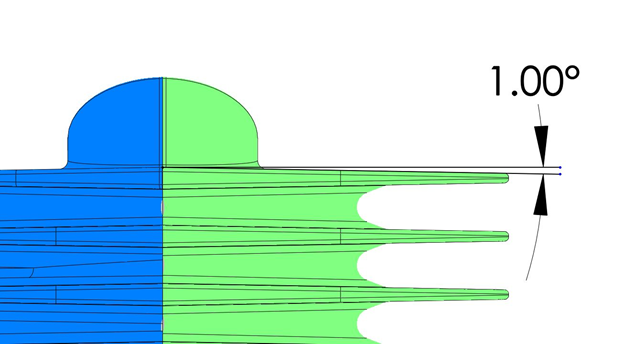
A cooling fin designed with 1 degree of draft.
2. Undercuts
Undercut features usually require retractable slide cores or secondary machining to form in a die casting. Undercuts will add to the complexity and cost of the die. Avoid undercuts in your design when possible.
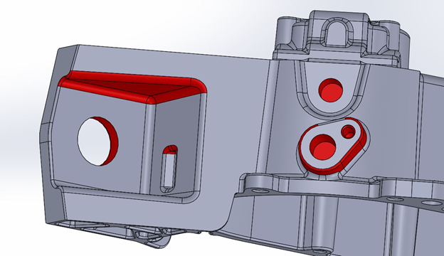
Red shading marks the undercuts on this design. Each one adds complexity and cost to the die.
3. Internal Features
Enclosed internal features include passages or pockets that don’t open in the direction the die pulls apart. The two die halves can’t form them alone, so they usually need slide cores or machining after casting. Avoid internal features in your die casting design when you can, or talk with your die caster early about the best way to produce them.
4. Datums
When possible, keep critical dimensions in the same die half. Dimensions vary more when they cross the parting line. The NADCA standards list typical tolerances for various features, and every die casting designer should have a copy on hand.
5. Sharp Edges
Break sharp edges with fillets or radii. Sharp edges create stress risers in the die steel that can cause cracks and premature die failure. They also reduce the metal’s ability to fill the cavity without defects.
Where walls meet bosses or other features, connect them with ribs and generous radii. This promotes metal flow and increases part strength.
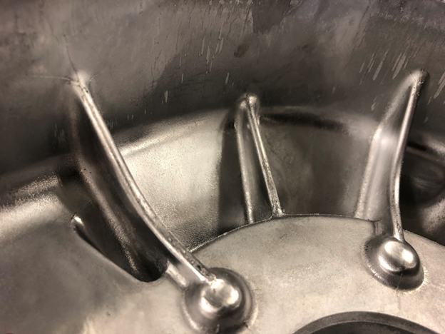
Ribs connect the outer wall to another feature on this casting, adding strength and improving metal flow.
6. Uniform Wall Thickness
Keep wall thickness as consistent as possible throughout the casting. Thick areas of a casting tend to have more porosity and will require additional cooling in the die. Heavy sections are also prone to heat checking in the die steel.
Use metal savers (cored-out pockets) whenever possible to remove mass from thick areas of the casting. Read our blog How to Make a Die Casting without Porosity for more on porosity.
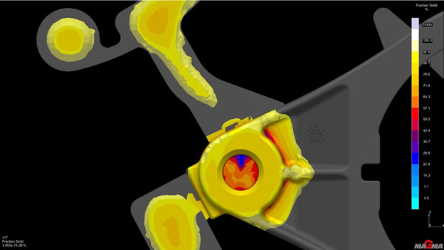
In this solidification simulation, a very heavy wall remains liquid while the gate and the rest of the casting have solidified. Porosity is likely to form in this area of the part.
7. Ejector Pins
The die uses ejector pins to push the casting out evenly. Design the part with ejector pin locations in mind. Space the pins evenly around the part so it releases without bending, and place them on bosses, ribs, or other sturdy features. Pins placed on a thin wall can distort the part or push right through it.
8. Final Machining
If your casting has features that can’t be die cast or need very tight tolerances, final machining will be required. Keep the amount of material removed to a minimum. The more material removed during machining, the more likely porosity will be exposed on the machined surface. Remove just enough to account for dimensional variation in the castings.
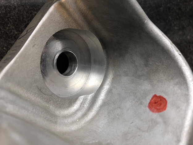
A deep bore machined into the casting. Porosity can be expected when removing a large amount of material.
9. Parting Lines
Consider the die-casting tooling when designing the part. The casting will have parting lines where the cover and ejector die halves come together, as well as at any moving slides. Visualize the parting lines and avoid features along them that create complicated steps or require slides. These features can often be cast, but they will increase tooling and casting costs.
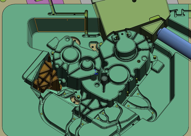
An ejector die with a complicated stepped parting line.
10. Thin Steel Conditions
Visualize the die steel and the parting line. Some features, such as cooling fins, require thin steel blades in the die. These die features wear quickly and need frequent maintenance, increasing die, replacement parts, and casting costs. Avoid features that create thin steel conditions when possible.
Why Your Die Caster Belongs in Casting Product Design
If your design follows these 10 concepts, it has a good chance of being die cast successfully. Working closely with your die caster is still the best way to keep costs down over the life of the part.
Draft, wall thickness, and parting line location are all easier and cheaper to change on a drawing than in die steel. When the die caster is part of casting product design from the start, tooling and quality problems get caught before the die is built.
Partner with General Die Casters on Your Next Die Casting Design
At General Die Casters, part of the GD Casting Group, we use our experience and technology, including MAGMA flow simulation, to help customers design parts that can be cast with the highest quality and the lowest cost. That’s how you reduce tooling and casting costs over the life of a project.
Have a new design or an existing part you want to improve? Contact General Die Casters for advice on quality and cost.
Die Casting Design FAQs
What can I do instead of designing an undercut?
Start by checking whether the feature can be turned so it opens in the same direction the die pulls apart. Moving the parting line can sometimes do the same thing. If neither works, compare the cost of a slide in the die with the cost of machining the feature after casting. Slides add moving parts that need regular maintenance, so machining can be the better choice for lower volume parts.
What happens at the parting line on a finished casting?
A thin layer of metal, called flash, can form where the two die halves meet. It is trimmed off after casting, but a small witness line usually remains. When possible, keep cosmetic surfaces, sealing surfaces, and tight tolerance features away from the parting line.
What should I send a die caster for a design review?
Send a 3D CAD model, the alloy you plan to use, expected annual volume, and a drawing that marks critical dimensions, tolerances, cosmetic surfaces, and machined features. With this information, the die caster can run flow and solidification simulations to spot porosity and fill problems before any steel is cut.